
The assignment for this week is to design and build a wired &/or wireless network connecting at least two nodes For this week's , I desired to building a wired serial network using redesigned hello.bridge board and two hello.node boards
In this week I decided to build a wired serial network. I start to study about serial communication
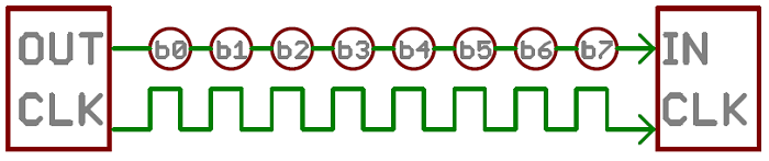
Serial communication is the process of sending data one bit at a time, sequentially, over a communication channel or computer bus. This is in contrast to parallel communication, where several bits are sent as a whole, on a link with several parallel channels.
Then I start to design one bridge and two node boards
First I Download all the necessary files including the C file, the makefile, hello.bus.45.bridge (board) & the hello.bus.45.node (board . then i start to design modified version of the downloaded board
First I start to design Bus bridge
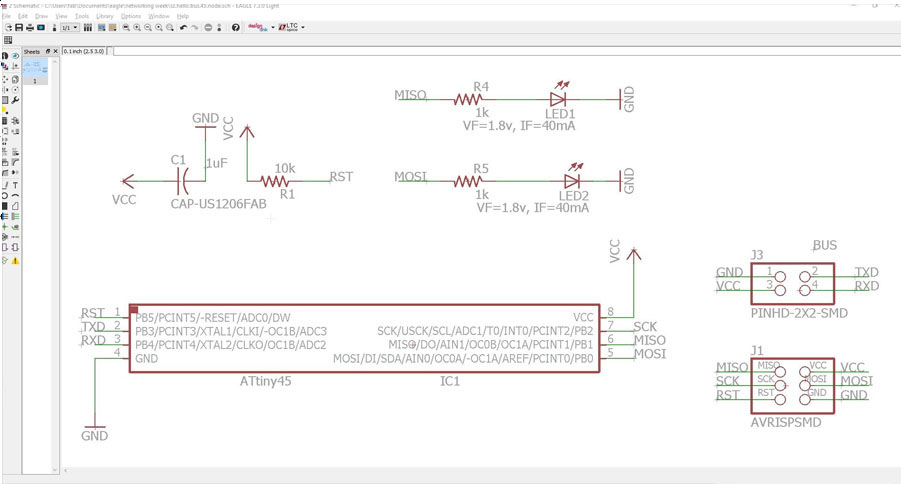
. I used Eagle CAD to create a modified version of the ATtiny45 based hello.bus.45.bridge.cad design and added an extra LED to board .
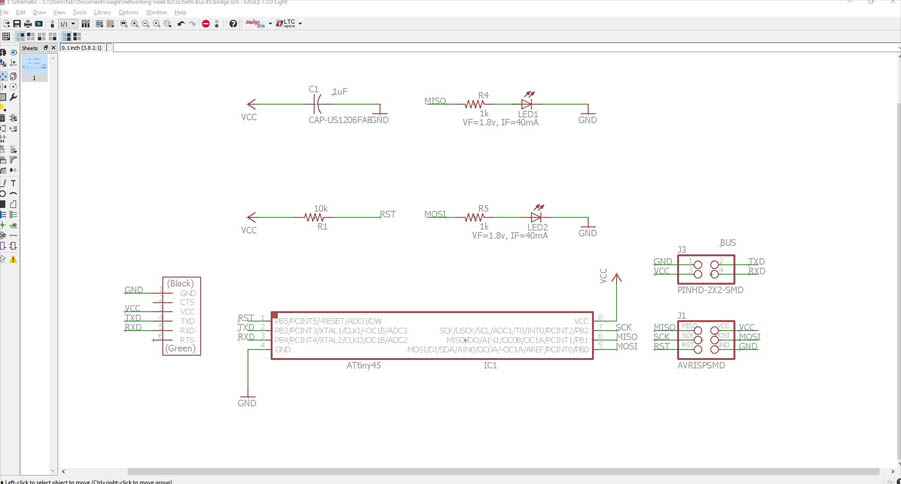
Schematic for bus.45.bridge
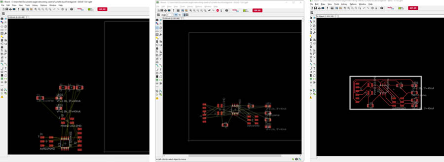
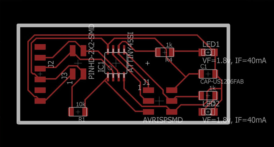
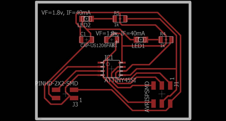
Board layout for bus.45.bridge
Download designed eagle files of bus bridge from here
Download bus.bridge.45.sz.with2leds.c - AVR C program
Bus node #1
Then I desired to create a modified version of the ATtiny45 based hello.bus.45.node.cad design by adding a second LED
Schematic for bus.45.node
Board layout for bus.45.node
Download designed eagle files of bus node#1 from here
Downloadbus.node.45.sz.with2leds.pb.c - AVR C program
Bus node #2
I decided to design a version of the bus node with two LEDs, a pushbutton, and a photo-transistor . For this bus node I using an ATtiny44 micro controller so that I could add additional input and output features.
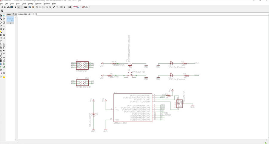
Schematic for bus.44.node
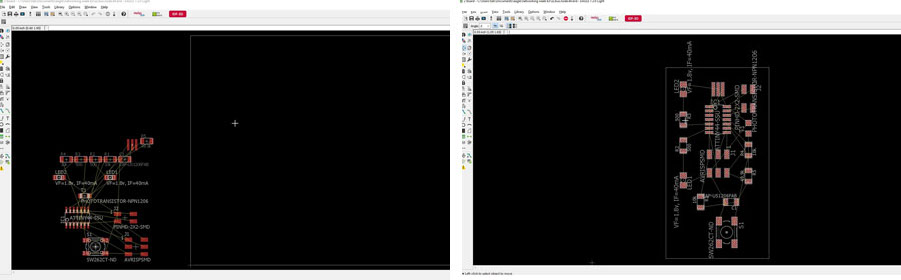
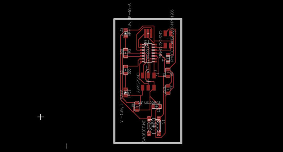
Board layout for bus.44.node
Download designed eagle files of bus node#2 from here
Download bus.node.44.sz.with2leds.c - AVR C program
Milling and staffing the board:
After I finished milling one bridge and two nodes I solder the components on the boards

Modifying the C code
1 . modify " hello.bus.45.c " code for each node in the network
In my network i have two nodes and one bridge ( the bridge board with FTDI is technically a “node” )
2 . In network need different node id for each node
In my net work I set the id " 0 " for bridge , id " 1 " for node #1 and id " 2 " for node #2 in “hello.bus.45.c”
In the C code make change on the line
#define node_id '0'
Save the file
Next modify the C code again and change node id to 1
,then save
Finely modify the c code , change node id to 2
Download modify the C code for bridge from here
Download modify the C code for node 1 from here
Download modify the C code for node 2 from here
Programing the boards
To generate .hex file and programing , i just follow these steps.
open a terminal and navigate to where the code is downloaded too. Then run the following commands:
1.) avr-gcc -g -Os -mmcu=
Tthis produces an object file called flash.o which then needs to be linked using
2.) avr-gcc -g -mmcu=
this has now produced a binary file called flash.elf, which is a GNU executable file. we gotta mess with it a bit more and grab some bits out of it to make the hex file
3.) avr-objcopy -j .text -j .data -O ihex file_name.elf file_name.hex
In the folder you wull get your .hex file
Now programing to ic using avr-dude , follow these step
4)sudo avrdude -p
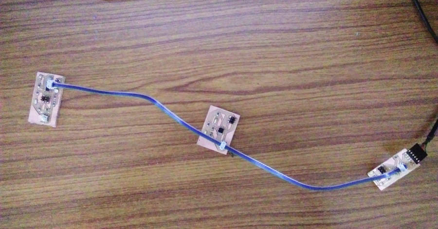
Setup the network
After programing all the nodes I put them on the network using bus cable . FTDI cable connected to bridge
For communicating with nodes first I use term.py ,The program term.py worked but all three nodes just sat there doing nothing
Then I try with Arduino IDE.I opened the serial port in Arduino , making sure the correct FTDI port is selected, and set the rate to 9600 then I entered the ID No..
Problems Faced:
No values are transmitting or receiving from the boards to the serial monitor. I solve this problem by setting correct bit rate on serial monitor